| LiMBO Links | Join Now | LiMBO-Mart |
| VANAGON HEADLIGHT RELAYS - WHY? & HOW? by Frank Condelli
The reason for this is very simple really. The
Vanagon A simple cost efficient solution to this problem is to install relays to transmit the voltage and amperage necessary to properly and safely illuminate the standard headlamps or whatever more powerful headlamp bulbs you would like to use. The Vanagon's original headlamp switch will be used to activate the power to the headlamp dimmer switch which in turn activates the power to the relays of either the high or low beam depending on the position of the dimmer switch. Also, a clean-up of the ground return path of the headlight circuit is advisable for proper operation. You can either buy pre-wired ready made headlamp relay kits for Vanagons. I have them on my website at www.frankcondelli.com as do any one of the many other Vanagon parts sellers on the Internet. Or, you can make them yourself. To build them yourself you will need two 12 volt, 40 amp minimum standard automotive four pin relays of good quality, two relay sockets for these relays either generic or VW OEM ones that snap onto the relay box of the '86 —'91 model Vanagons relay box, female spade terminals for the relay sockets, 12 and 14 gauge wire, butt connectors, insulated and non- insulated female spade terminal ends, and a good terminal end crimper that works for all types of terminal end connectors including the special terminal end connectors for the relay sockets and a good wire stripper. A complete detailed list of components follows at the end of this document. |
There are two wiring plans that follow
also, one for the '80 — '85 Vans and one for the '86 — '91 Vans as their
fuse boxes and wiring are different.
Parts you will need: 1980 —1985 Vanagons Note: the colors of the following wires are only to aid you in keeping things easy. They can be any color you choose or have. 8" - #14 ga. wire, stranded copper, yellow 1986 — 1991 Vanagons Note: the colors of the following wires are only to aid you in keeping things easy. They can be any color you choose or have. 16" - #12 ga. wire, stranded copper, red Installation Procedure for 1980 - 1985 Vanagons 12 gauge yellow wires from both relay terminals #30 goes to position
# 7 as described below. Remove the Vanagon's fuse block from the firewall under the left-hand corner of the dash by removing the large Phillips head screws on the mounting bracket. On the reverse side of the fuse block you will find at fuse position 7 a spare male terminal end, on the fused side of the fuse, where you can pick up the necessary 12 volt fused power supply for the headlights. Some people |
suggest that it is better to drag an all
new 12 gauge wire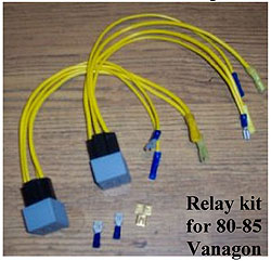 from the battery using a new inline fuse for this
circuit but I have not found that it is necessary. The original power
feed from the battery to the fuse box, if in good condition, is
sufficient to provide the current needed. Fuse 7 should have a 16 amp
fuse. Test with a 12 volt light tester to make sure there is 12 volts
present when the ignition key is in the on position. Using a double
terminal end extender connected to the free male terminal, connect one
end of each of the two 8” red 12 gauge wires with a from the battery using a new inline fuse for this
circuit but I have not found that it is necessary. The original power
feed from the battery to the fuse box, if in good condition, is
sufficient to provide the current needed. Fuse 7 should have a 16 amp
fuse. Test with a 12 volt light tester to make sure there is 12 volts
present when the ignition key is in the on position. Using a double
terminal end extender connected to the free male terminal, connect one
end of each of the two 8” red 12 gauge wires with a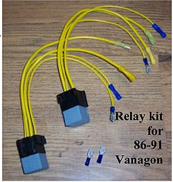 female terminal end
securely crimped on each end, to this 12 volt power supply terminal.
Crimp on a female spade relay socket terminal end on each of the
opposite ends of the two red 12 gauge wires then plug them into the
relay sockets so they line up with position 30 of the relays. female terminal end
securely crimped on each end, to this 12 volt power supply terminal.
Crimp on a female spade relay socket terminal end on each of the
opposite ends of the two red 12 gauge wires then plug them into the
relay sockets so they line up with position 30 of the relays.*NOTE* - For Safety reasons, you should disconnect the negative terminal from your battery after doing the test for power at the terminals if you feel unsure of yourself working with the electrical circuits involved. Next, take two 12" 14ga. brown wires and attach one 14 ga. female spade terminal end to each of them. Then attach one female spade relay socket terminal end to each of the other ends. Locate the round grounding block on the firewall above where the fuse block was located. There should be some empty male spade terminals. Plug the brown wires on them. Run these wires to the relay sockets and insert the two female spade terminals with the brown wires attached into position 85 on each relay socket. While there, locate the two brown ground wires from the headlamps which are terminating together in one connector. If there is more than one pair you can determine which pair is for the headlights by turning on the headlights then removing one pair at a time until the headlights go out. Cut the connector off and attach one female spade connector to each wire and reconnect each one to an individual terminal on the grounding block. This will improve the return path of the electricity from the headlamps. Next, looking at the rear of the fuse box, the side that was against the firewall before you removed it, find at fuse #4 the single 12 gauge yellow w/black stripe input wire coming from the hi/lo beam switch that goes to the two fuses of the low beams of the right and left headlights. This wire should have 12v power when the low beam headlights are on and low beam headlamp fuses, #3 & #4 fuses, are removed. Remove this wire from its connector, cut off the terminal end and crimp on a new female spade relay socket terminal end then connect it to one of the relay holders at position 86. Take the 8" yellow 14 gauge wire and crimp on a female spade relay socket terminal and connect it to the same relay socket at position 87. Crimp on a female spade terminal end to the opposite end then plug it on the terminal on back of fuse 4 where you previously removed the yellow w/black stripe wire. |
Next, looking at the rear of the fuse box,
the side that was against the firewall before you removed it, find at
fuse #6 the single 12 gauge white input wire coming from the hi/lo beam
switch that goes to the two fuses of the high beams of the right and
left headlights. This wire should have 12v power when the high beam
headlights are on and high beam headlamp fuses, #5 & #6 fuses, are
removed. Remove this wire from its connector, cut off the terminal end
and crimp on a new female spade relay socket terminal end then connect
it to the other relay socket at position 86. Take the 8" white 14 gauge
wire and crimp on a female spade relay socket terminal and connect it to
the same relay socket at position 87. Crimp on a female spade terminal
end to the opposite end then plug it on the terminal on back of fuse 6
where you previously removed the white wire.
Now, push the relays into the relay sockets. Then secure the relay holders to the fuse box or some other wires with tie wraps. Now you're done and ready for a test. Start the vehicle and make sure the charging indicator light is out. Turn on the head lamp main switch. Activate the dimmer switch to see if you have high and low beams operating. Test the voltage at the headlamp plug if you wish, it should now be higher. If everything is satisfactory replace the fuse block on the firewall being careful to position all the wires so that there is no strain on any of them. Enjoy your new headlamp power ! If you decide to use higher wattage bulbs in your headlamps after
installing the relays, you may find the fuses will burn out. If this is
the case then you can install higher amperage fuses in the fuse
positions for the headlamps. Use the next size higher amperage fuse. Do
not go higher than necessary to keep your new bulbs from burning the
fuses. Usually one size larger is needed and sufficient on the high beam
circuit only. Installation Procedure for 1986 1991 Vanagons
|
| Remove the Vanagon's fuse block from the
firewall under the left-hand corner of the dash by removing the two
large Phillips head screws on the mounting bracket. The metal mounting
bracket needs to come along with the fuse block to give better access to
the space behind. Install the two relay sockets to the top edge of the fuse block if using the VW relay blocks. There may already be one or two fuse sockets and one relay socket there. You can move whatever is there already so that you will be able to group the two new relay sockets side by side. To move the relay socket or fuse sockets release the two locking tabs that are holding them in their mounting. If using standard automotive relay blocks you can just tie wrap them with their relays anywhere convenient. Locate on the back of the fuse block the two red 12 ga. wires that are plugged to the two large male spade terminals on the fuse block. These will be on the lower left-hand corner of the fuse block. Just up from these two terminals are usually four unused smaller male spade terminals, sometimes some of the four are already used due to factory options or other owner installed accessories. You will have to deal with this situation on your own so that you can gain access to these terminals. Test them with a 12 volt light tester to make sure they have 12 volts present when the ignition key is in the on position. Some people suggest that it is better to drag an all new 12 gauge wire from the battery using a new inline fuse for this circuit but I have not found that it is necessary. The original power feed from the battery to the fuse box, if in good condition, is sufficient to provide the current needed. Run two 8” 12 ga. wires from two of these terminals by using the two female spade terminal ends crimped securely to the ends of the 6” 12 ga. wires, to the two relay sockets. Crimp a relay female spade terminal on the end of each of the 12 ga. wires. Then push them into position 30 on each relay socket. *NOTE* - For Safety reasons, you should disconnect the negative terminal from your battery after doing the test for power at the terminals if you feel unsure of yourself working with the electrical circuits involved. Next, take two 12” 1 4ga. brown wires and attach one 14 ga. female spade terminal end to each of them. Then attach one female spade relay socket terminal end to each of the other ends. Locate the round grounding block on the firewall above where the fuse block was located. There should be some empty male spade terminals. Plug the brown wires on them. Run these wires to the relay sockets and insert the two female spade terminals with the brown wires attached into position 85 on each relay socket. While there, locate the two brown ground wires from the headlamps which are terminating together in one connector. If there is more than one pair you can determine which pair is for the headlights by turning on the headlights then removing one pair at a time until the headlights go out. Cut the connector off and attach one female spade connector to each wire and reconnect each one to an individual terminal on the grounding block. This will improve the return path of the electricity from the headlamps. |
Remove the plastic cover from the underside of the
steering column, two screws and spring clipped in place, to expose the
wiring to the turn signal/dimmer switch. Locate the 12 ga. white and
yellow wires leading to the switch. Follow these two wires back to the
fuse block. Cut these two wires so that the four resulting wire ends
will reach the relay sockets. Crimp a female spade relay socket terminal
end onto each of the ends of the four wires. The yellow wire from the
switch goes to position 86 on one relay socket and the yellow wire from
the fuse block goes to position 87 on the same relay socket. The white
wire from the switch goes to position 86 on the other relay socket and
the white wire from the fuse block goes to position 87 on the same relay
socket. Now you’re done and ready for a test. Start the vehicle and make sure the charging indicator light is out. Turn on the head lamp main switch. Activate the dimmer switch to see if you have high and low beams operating. Test the voltage at the headlamp plug if you wish, it should now be higher. If everything is satisfactory replace the fuse block on the firewall being careful to position all the wires so that there is no strain on any of them. Replace the steering column plastic cover. Enjoy your new headlamp power! If you decide to use higher wattage bulbs in your headlamps after installing the relays, you may find the fuses will burn out. If this is the case then you can install higher amperage fuses in the fuse positions for the headlamps. Use the next size higher amperage fuse. Do not go higher than necessary to keep your new bulbs from burning the fuses. Usually one size larger is needed and sufficient on the high beam circuit only. Also, check the condition of the bulb sockets. Often as these vehicles age the wires and connectors in the headlamp sockets are corroded especially in the ‘86 ‘91 models and will add resistance which impedes proper illumination of the bulbs. Sometimes they can just be cleaned with phosphoric acid and sometimes it is necessary to install new pigtail sockets. These are usually available from any good automotive store such as NAPA. Try to get the best quality ones you can and ones with 12 ga. wires are preferable to those with 14 ga. wires. When installing these pigtail sockets use heat shrink covered butt connectors to insure a good sealed joint. Frank Condelli Frank Condelli & Associates |